|
MODEL 7041 FLANGE ADAPTER- PN 10 / PN 16
The Model 7041 Flange Adapter allows for a direct connection of PN 10* and PN 16 flanges. The specially designed gasket enables the transition from a grooved system to a flanged system or component with this single flange adapter. The two-segment design provides an easy and fast installation. 2” through 12” (50 mm – 300 mm) flange adapters are supplied hinged as a single assembly, while 14” -24” (Model 7041N) are supplied with two separate segments and a draw kit. All include an EPDM rubber gasket and plated track bolts and nuts. Housing segments are supplied with our standard painted finishes, i.e. orange or RAL3000 red. Optional finishes such as hot dipped zinc galvanized and custom epoxy coatings are available.
* PN10: 2” - 6” (50 mm – 150 mm) only.


Note: 2" - 6" flange drilling to PN 10 / PN 16 and 8" and above to PN 16.
* Working Pressure is based on roll grooved standard wall carbon steel pipe.
MODEL 7041N FLANGE ADAPTER - PN 16, 14" ~ 24"
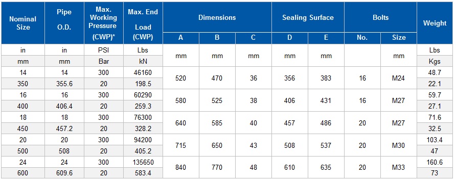
* Working Pressure is based on roll grooved standard wall carbon steel pipe.
Important Notes:
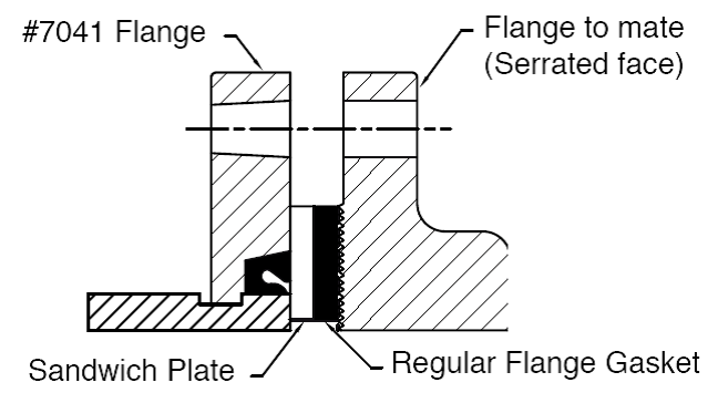
1. The Model 7041 flange adapter requires a hard flat face for effective sealing. Sealing surface D is the maximum inside face requirement, sealing surface E is the minimum outside face requirement. If the mating flange face is outside these dimensions, a flange gasket and model 49 sandwich plate (Model #49, see cut sheet #V-03) must be used. With the serrated faces of some valves or rubber-faced wafer valves, the mating surface might also be inadequate and a sandwich plate must be used.

2. The Model 7041 flange adapter has small triangular teeth inside the key shoulder to prevent the pipe from rotating. These teeth should be removed when being connected to schedule 5 pipe, plastic pipe or components or surfaces that could be damaged by these teeth.
3. The Models 7041 flange adapter shall not be used as anchor points for tie-rods across non-restrained joints.
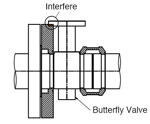
4. When assembling a Model 7041 flange adapter against a butterfly valve or ball valve, make sure that the outside diameter of the flange adapters do not interfere with the valve actuator or the mounting pad of the actuator.
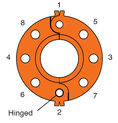
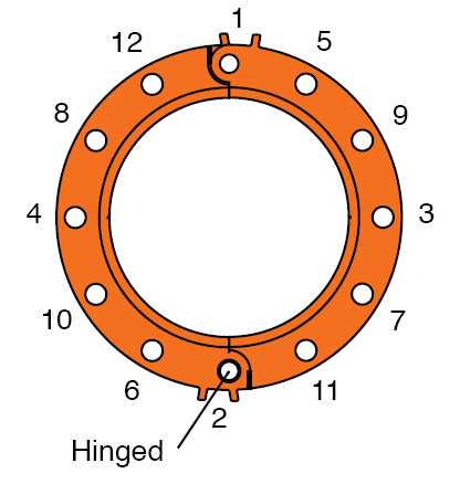
5. Bolt tightening sequence: Like a regular flange joint, it is important to make flange faces contact parallel. Tighten nuts alternately in the sequence of diagonally opposite pairs as shown below until the flange faces meet and make a metal-to-metal contact. When using two model 7041 flange adapters to mate pipe, or wafer / lug valves, the hinge point locations must be staggered 90° to each other, a model 49 sandwich plate must be used where appropriate, and flange adapter segment housings must remain parallel during nut tightening sequence.
|